Two years ago I came across G5 project. At the time it seemed to me like
a rocket science, i still had complications with the hum and noise in
TT pedals.
But then my friend, who is dedicated guitar player and
tube fan, announced he is getting married - and I made a promise I would
make him an amp head for his wedding gift. Approximately a year ago I
had some time and made a plan to the extent that I did all the needed
shopping. From the very beginning I had certain mods in plan, so I
didn't order the "all inclusive" kit, but bought parts separately.
Almost
a year passed before i was able to dedicate myself to the project
again. So the friend is already married - but with all the parts there
was no turning back!
So after quite some hours of work here is my rendition of G5 amp.
With following mods /variants)
- DC heater
- LineOut (as in version 1)
- Send/return is omitted but possible to add, as there is a jumpered conector on the preamp pcb
- Q regulated bias (Dymo mod) - with typ3055 transistor
- swithable "safety resistor" on the output of OT
DC
heater was qite a task, since EL34 draws 1,5A when hot and even more
when cold. First I planned to use a MIC295092 circuit, but then a friend
gave me a cheap DC/DC stepdown module with 3A threshold, which is quite
enough (and there is really no need for perfectly clear DC for the
heaters, just not grossly noisy), and I hooked it after a gretz bridge
and a prominent 10uF cap - I was afraid there would be problems, because
the bought mains transformer had 8VAC output (I tried to plan voltages
as close to the needed as possible to avoid too much of a dissipation of
then planned linear regulator - so I used low dropout diodes on the
bridge and planned to use low dropout regulator -well, now I know I
shouldn't be so afraid of an IC warming up a little (or 100°C), and
there are also heatsinks ... So, quite a lot of complication for nothing
... well, nothing, I learned: a little overvoltage is easier to
regulate and cool down than to get good linear out of too small of a
boundary. Well, when all hooked up, the DC supply is quiet and nice. On
precisely 6,3VDC, grounded from the module to star ground. My headphones
hear nothing. Ozsi shows some noise on micro scale. So, I can call it
sucess. For the next time: plan power transformer heater secundary with
few volts overhead so there would be no need for monster filter cap and
low dropout bridge diodes.
To be able to plan the "guts" without drilling (and ruining with
mistakes) the chassis, I made the model from the cardboard box. It
proved really fantastic, much more sturdy than I thought it to be.
Before that I made all plans for my projects in Corel Draw, and it was a
time consuming work, but still prone to mistakes - it was much easier
to work with real components - and much more fun. So all the wires, all
the "modules" and parts could be positioned and dimensioned correctly
(but still I made some stupid things haha).
The biggest issue was preamp board etching and drilling - the later much
more. I don't know, is it me, are the late hours in which I was working
on the project or it is a common thing, but almost no 1mm hole was on
the right place. For the etching I used a lack paper (from net from
China) and pressed toner on the copper board with the help of salvaged
copier fuser (I don't like to ruin my laminator; this was a separate
project of mine which turned worse than I thought - on a salvaged fuser I
mounted a 250°C thermostat instead of thermal fuse, but I have problems
with the wheels assembly, not sure why. Still, it works quite good) .
To be on the safe side with the crappy preamp board I tinned all the
traces. I also put rivets in mounting holes for tube socket (so it was
easily soldered on the "wrong" side) and also in all wire terminations
(to be able to remove them any time without ruining the traces).
Populating the board was easy work then. I have put also complete tone
stack on the board - as I always leave the notches on the pots I don't
beleive there is much damage done to the board through pot fiddling. But
the tube socket it the other question - there is no chance you would
put in or out the tube without holding the board - so for the next time:
build point to point (preamp is really straightforward easy), or at
least plan screw attachment holes very close to the socket.
I was afraid, if the biasing board would really work (I am not used to
work with sand), but it was OK. Still it would be much simpler to use a
250kLin more powerful pot. But, as it works, this design could be used
on all the other future projects ...
"Switchable safety resistor" was part of the plan the whole time, the reasons are two:
1) Filip is my friend. I wouldn't like him to ruin his amp's OT by not plugging in the speaker
2)
G5 is a weak amp - to get the real "sound" it should be connected
through "line out" to a more powerful power amp - and then it is a
nuisance to plug in its own speaker
So I bought a 50W 7,9ohm power
resistor and mounted it on a switchable jack for the speaker out. I was
afraid if I did all correctly, because OT's are not cheap stuff. But, it
works.
I have managed to wire the line out pot in opposite (how?!?), but as it works, I will not resolder it.
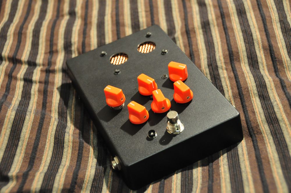
Final result?
The first thing, looks are amazing (let us ignore my
ugly handwriting, OK?). Hammond made a fenomenal job with the chassis
cover, and you don't need a lot to make the amp look like a boutique
hi-fi. The "G5" letters are from automobile part of harware store, and
look just right. I have put the main power led on the top of the chassis
to make leads as short as possible (from the DC heater supply), but
with the amber led the looks are fenomenal - amber glow of led mixes
with amber glow of power tube and it's just - magical ... Power resistor
on the back protrudes from the main shape, but not too much, and looks
like some alien "super powered" add-on. There are some drill holes which
I made out of stupidity and sloppyness, but don't bother too much.
The
guts look messy as hell, after I made it I was quite ashamed of it,
compared with neat insides of other amps on the net. But still,
everything is on right place and there is claritiy of logic; the sonic
results correspond with careful design (perfected star ground near the
input jack, safety distances between modules, generous separation of
signal, power and GND wiring). For later projects I work more with solid
wire to ensure more neat wiring. Oh, I used speaker wire for heater
supply - I am a serial overkiller, if you haven't noticed yet.
The
other overkill are the capacitors: I parelelled practically all power
caps with lower poly ones: for the power tube, by the OT, and used only
10uF poly for the preamp ... Probably this is far too much, but I don't
know a reason this could be wrong.
You probably noticed, I am a
"chocholate freak" (at least in Slovene electricians call those plastic
enclosed screw terminals chocholates) - they are probably not very good
in the signal path, but with high voltages in power sections they are
perfect for modular building. And there are allways few there in your
box. Around the OT I used them to enable easier switching between
primary and secundary windings - if they prove unreliable through time,
they still can be replaced with terminals. But, jacks are also just
slide contacts, right? In power section use of "chocs" is logical - why
solder (and then desolder, and solder ...), when screw terminals work
just fine. The whole rectifier board is based on those chocs, because I
planned to etch it, but then didn't feel like it. Later I will use
cancaps with solder lugs attached to the chassis and also the bridge -
this board is a disgrace and is bulky (and don't ask me how to remove it
from the chassis). You can see the power supply is not on one place,
but near the corresponding modules: a)rectifier with reservoir cap b)
power tube caps (with all the psu resistors) c) preamp cap d)OT cap
(parelell to reservoir cap) e) caps of DC heater. Behind is the logic,
that caps must be close to parts they supply (to "embrace" the circuit).
Sound:
I hoped for a low noise build, but such ... It is a
success. There is no hum, no mains, on both knobs at full there is some
static, but, it's on the level of "out of shop" amps ...
At full
gain overdrive is magnificent, with correct adjustments on the guitar
you can get crazy things. And if you also add banana booster in the
sound chain ... Sweet!
Clean sound is nice, but weak. Real tubey
sound, but not at band practice volume. 25W max dissipation SE design
has it's toll. Here comes handy line out jack, and with the connection
of external power amp you can hear the sweetness. Tone stack is less
effective than expected, with the "sweep " switch practically
unnoticeable (is there some mistake?)
next builds (if when and why - takes lot of money and time):
- preamp
in point to point arhitecture (not Fender like, but "real" ptp, with
components directly on the socket, and supported with singular terminals
on other side - also the TS in PTP >> on pot lugs
- rectifier: "cube" bridge and can capactior attached to the chassis
- 9VAC secondary for the heater (to use normal diodes), maybe separate DC/DC modules for preamp and power sections
- connections made with solid hookup wire for neater (and less parasitic /capacitance) problematic guts
- bias board made on protoboard
- power psu made on terminals
- OT connections made on terminals
- use rackomount chassis with internal brackets - not so beautiful, but significantly cheaper, makes the amp more useful
>>forgot:
- I used a custom made power transformer - toroid, which was 28€, much less than original
-
regarding the sound: I suspect the treble is some way attenuated, but
this could be also due to the fact I tested the amp mostly on my bass
cab
//


 ) jacks, knob, led, switch, wires ... Not a thing someone wouldn't have
as remains ... Chassis, pot - missing > ordered (can wait). The
model in cardboard was made in approx. 2 hours. With direct PTP approach
- my way: messy as hell and hard to troubleshoot, also prone to
parasitics, but small. When the chassis arrives there is a complication,
because the insides are smaller than thought. When plugged in, sound is
great, practically no noise. This kind of tube booster on the begining
of sound chain is practicaly all the tube in it you need ...
) jacks, knob, led, switch, wires ... Not a thing someone wouldn't have
as remains ... Chassis, pot - missing > ordered (can wait). The
model in cardboard was made in approx. 2 hours. With direct PTP approach
- my way: messy as hell and hard to troubleshoot, also prone to
parasitics, but small. When the chassis arrives there is a complication,
because the insides are smaller than thought. When plugged in, sound is
great, practically no noise. This kind of tube booster on the begining
of sound chain is practicaly all the tube in it you need ... 


