Some other time I bought a 40W Kemo power amp module, I thouht about using it as an amp for an active monitor, for my uncle's tractor "radio" or someting like that. I was kind of interested, how such thing works. Few months ago I began experimenting with it and got quite a "clean" playback if I connected it to my cellphone. (Kemo module - https://blogger.googleusercontent.com/img/b/R29vZ2xl/AVvXsEhrGZDSl3OZV56ebl51dr9H_IGWkjgdXbvdyeqz7_-6KUBg5EohHU3GRaglK-QoBiFZXsv05zh6_9jEm_LSLRuUwe5IJYQSR89GxCUJ1TC9rkP2raMSvEws4MQSPyr8sSQVAgpg7H4grS8B/w1534-h863-no/DSC_0127.jpg)
Also few months ago I assembled (just on breadboard) my first LDO PSU for the tube heaters. (When I made my first TT projects, it was with suplied and presented PSU, which uses a LM7812 fixed regulator. Because I wanted to regulate the heater for octal lamps like EL-34, which use 6,3V and (hot)~1,5A, LM7812 was not suitable. Because of high currents involved (which even at smaller voltage dropouts create a significant heat and so demanding cooling solutions for the regulating IC, I went into LDO (low dropout) adjustable regulators. First I read about LM108* class, but bigger ICs were pretty expensive. Then, when I stopped to be afraid of more than three pins on the component
 , I found Micrel 29502 adjustable regulator and bought a few on xxxx. I assembled a design on bredaboard and it worked. - https://blogger.googleusercontent.com/img/b/R29vZ2xl/AVvXsEjsVTw6Qcl-N3F0Rvp2L47Xx7kkHzsX_-dJBAHwASHzZS-lXKui_Eh0Bq_AX_aVs0DAKqvzoA9buFhltulmE-aJVnnBHDSWFAJXNn62hdLVpzYJIqBiGQUB2ACyVNakA_bIvPyf98bdg9PW/w332-h288-no/micrel.jpg
(probably I will write a separate post about that PSU, as it is quite
good (well, not really cheap), but I also have some problems)
, I found Micrel 29502 adjustable regulator and bought a few on xxxx. I assembled a design on bredaboard and it worked. - https://blogger.googleusercontent.com/img/b/R29vZ2xl/AVvXsEjsVTw6Qcl-N3F0Rvp2L47Xx7kkHzsX_-dJBAHwASHzZS-lXKui_Eh0Bq_AX_aVs0DAKqvzoA9buFhltulmE-aJVnnBHDSWFAJXNn62hdLVpzYJIqBiGQUB2ACyVNakA_bIvPyf98bdg9PW/w332-h288-no/micrel.jpg
(probably I will write a separate post about that PSU, as it is quite
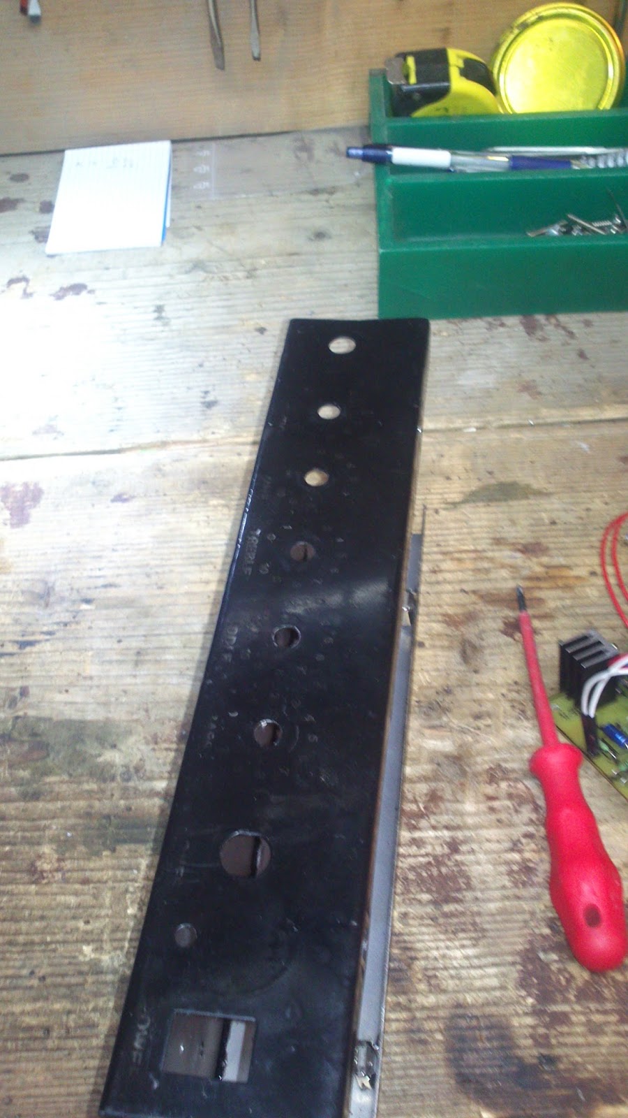
good (well, not really cheap), but I also have some problems)With a functioning PSU design and a poweramp module there were two things yet missing for the whole amp: trafo and a preamp. I took a trafo out of non used halogen lamp, which had standard 11,8VAC output and was rated for 3,95A. Now, when I use the amp, this trafo gets pretty, pretty hot and I am not sure about the reason for that. It surely wasn't designed for such a task, but trafo is a trafo I presume (if there is somebody able telling me what is happening I would be happy to know; the thing I saw was that at the input clips of the trafo I think on the primary side there is something like a small resistor - maybe a thermistor for the softer start of the lamp (which has insanely low resistence when cold as far as I know) - if it is a thermistor, everything is pretty clear - you can se the schematic sign on the photo - https://blogger.googleusercontent.com/img/b/R29vZ2xl/AVvXsEj5sADTF6SwrSGcUE6Qw0QVZW7drgjoQeBFmxYbqvBS5E8ZUlqufkiXr8XE7pwYzU2kCQgN4pGTR0rt1EL-OLc89CPbZMiT0Lq1FwfRo01q5zGTv6EpyWS7IROdhv3dCgBpka0nQBu-qFkY/w1534-h863-no/DSC_0129.jpg). I mounted the trafo outside the chassis (there was not enough room inside + trafos can be quite a noisy devices).
For the preamp I decided to use a TT kit Vanilla Overdrive (which I never assembled before - https://www.tube-town.net/cms/userfiles/media/lov-vanillaoverdrive/lov-vanilla-schem.jpg). Surely I needed to change some things. I changed footswitches to toggle switches. First I thought about using another switch to bypass the transistor, but then I would have to drill additional hole in the chassis and I just didn't feel like. The main change was, that I moved the volume control so that it controls both channels (changed P3 to fixed 100k resistor and used a 1M audio pot instead of R20). Because of space considerations I also used much smaller caps (low voltage Wima) than in the kit (I'm not sure, how this affected the sound - later about that).
I decided to combine PTP and PCB methods (I am not very good and precise at drilling so it would be hard to match the pcb to already drilled holes for the pots and switches; also I really didn't find a usable 90° PCB mounted switch. So I made a PCB with toner transfer method. There was a nasty emergency during the etching process, which caused me to leave it in the liquid for quite a long time - the traces are "eaten away" in many places (I am still not sure if it wouldn't have been better I made a new plate at the time). I drilled the holes in a hurry, so I destroyed a lot of pads with my 1mm drill (I bought a 08 and 05 drills later and figured out that there are only few components, which have their leads thicker). So the process of soldering was a hardwork, with a lot of improvisation and possible cold joints. Until I started using PCB rivets -they solve the problem with destroyed pads or discontinued traces excellently. It is quite a costly solution, but great, specially for later resoldering and you can easily attach components to both sides of the board - soldering the tube sockets to the bottom of the PCB was kid's play) Still I am not really sure about the quality of the solder joints. When the plate was finished and populated I started working on "PTP" part of preamp: input jack, first cathode bypass switch (combined with LED), drive pot, tone pot with a smaller PCB for two caps and a resistor, switch for "channels" (practicaly bypassing all of the preamp or not), master pot and output jack. Then I tested the device and there was nothing happenning. When using external PSU, there were at least LEDs lit, but no sound coming through at the "non bypass channel" setting and quite poor at the bypass channel. I was desperate, but then I found out: 1) there was a cold joint at the enable pin of the regulator 2) I used the wrong resistor for "programming" the output voltage (which caused sudden jump of output voltage from minimum to maximum, when I reached the end of regulation pot) 3) (I am deeply ashamed) I made mistake when drilling the holes for the tube socked and so rotated the socket for one pin (pin 1 of the tube went to socket 2 - what do you think, could that ruin a component; specially the transistor? what could be the consequences of such a mess? ) Anyway, luckily I used the rivets, so there was really not much effort needed to remove a socket with a desoldering pump). When I corrected all three mistakes there was still much noise on the line, but the system was working.
Next stage was additional drilling of the chassis. It was not really a masterpiece and I had many problems with mounting holes later.
Then I began to lay cabling for power supply: from the inlet (with the fuse1) to the switch and than to trafo, from the trafo to second fuse and than to the PCB / PSU. Then I mounted poweramp module with the cooler on the outside of the chassis (my clumsy drilling, yuck!) Mounting the PCB in the chassis was more work than it shoud be, because of inaccurate drilling (I know now it is best to drill holes, if you dont own a CNC, with an unpopulated PCB). The last task was connecting power to the PCB (I twisted the wires), connecting the output jack (swithed) to the power amp and conecting all the grounding wires to the "star" ground point. Then final assembling.
The thing works and is quite impressive on "bypassed" channel (nice rounded tube sound with a bit of overdrive at higher volume), but is noisy as hell at "non bypassed" setting. It also has a nice "reverb" effect, which gives fantastic "space" to the sound. The sound on "non bypassed" is really not dependent on "drive" setting and goes to terryfing cracks when volume dial is over 12 o'clock. The overdriven signal is othewise nice, smooth and full. But gets practically lost in hissing, static and cracking. I intend to ask a friend with degree in el. engineering for help, but it could be:
a) cold solder joints
b) wrong use or lack of shielding (I think I overdid, but I am not sure)
c) damaged components, specially transistor, from the misoriented socket
d) mistake in grounding design (I think I overdid there also ...)
e) another collosal mistake in the style of already mentioned (and corrected) mistakes ...
Do you see anything in the pics? Any Ideas?
Al in all, when on "bypass" channell, the amp is very noiseless, but still: what to make it even quieter?
//
from TT Forum


Ni komentarjev:
Objavite komentar