
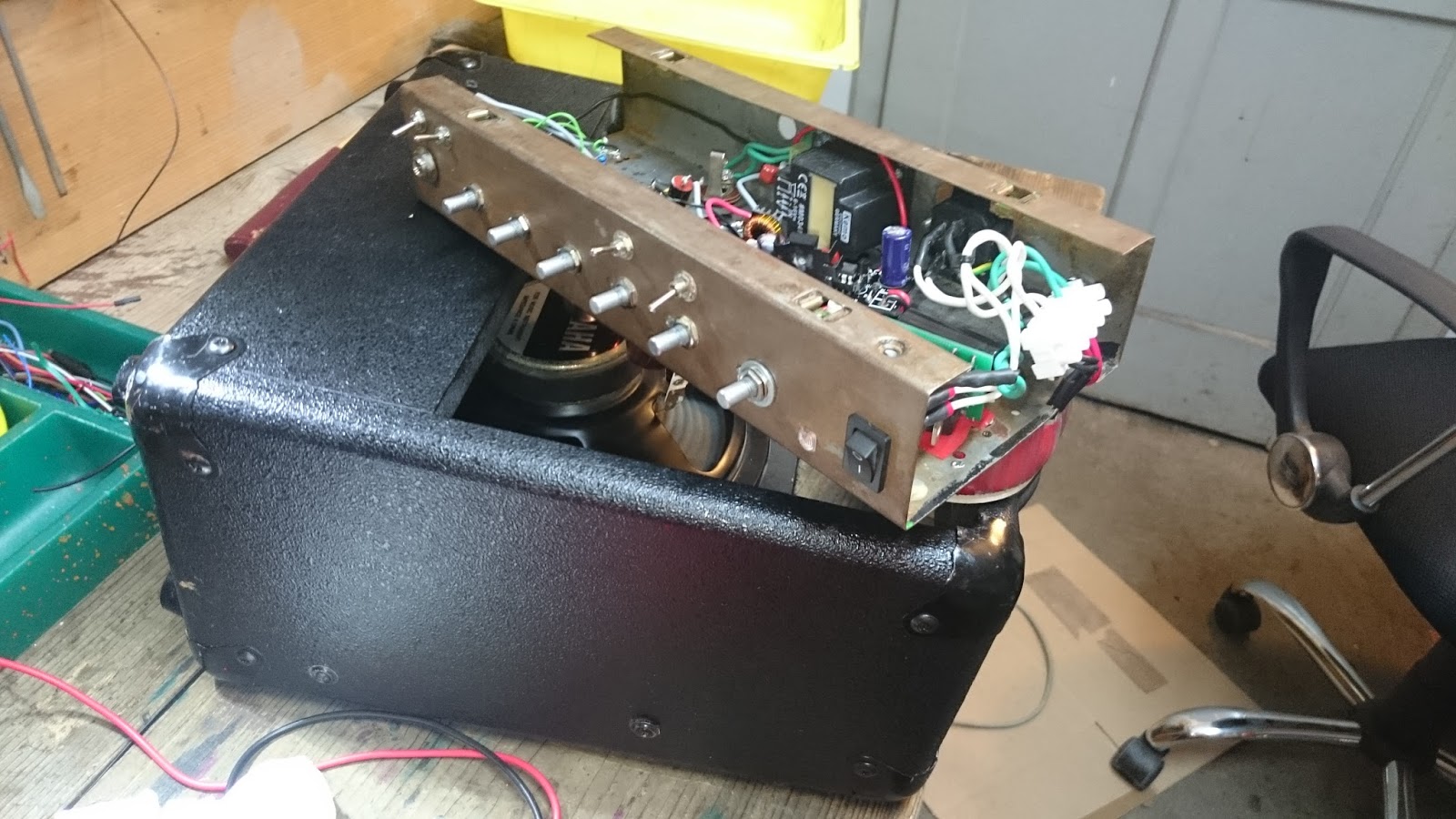
So here is "renewed Yahamaha", the "dIRT EDITION". Yes, you guessed, it is noisy as hell. Maybe someday I will make some order in this chassis. For now it was just a practical experiment, how Alembic bass preamp works (I really wanted to build it for a long time!) - with TT Vpump all this became much more simpler, because I only needed some generic components to build it, even PT was ordinary lighting 12VAC (50VA). It works great and is pretty loud. Master pot behaves funny in a way, it makes much less volume difference than expected. Tone strack works fabulously (but I becoma aware of HV present in it only in the process of buliding - I would better use some heathrinking from now on)). In front of Alembic there is a bypassable TT Banana booster circuit. With pots set up carefully it can serve as a nice overdrive effect. But sure enough this project gets quickly in the area of extremely ugly saturation /overdrive, where the sound decays. BUt with the correctly set-up pots both the clean and overdriven signal are not only satisfying. When you roll to 10 o'clock all the gain pots, switch to the bridge pickup and tune the tone commands, this monster weeps so convincingly that somebody would adopt it in a moment ... But it is mine!

Specs / build parameters:
- old fried amp's chassis, cab and speaker
- removed previously installed TT Vanilla circuit (look at the first few pics), because only bypass channel worked (I was thinking of troubleshooting it, but then the idea came to me to use long planned Alembic circuit - and TT Banana, which satisfied me as a stompbox)
- (unsuccessfully repainted the chassis few times, then began experimenting with "browning"
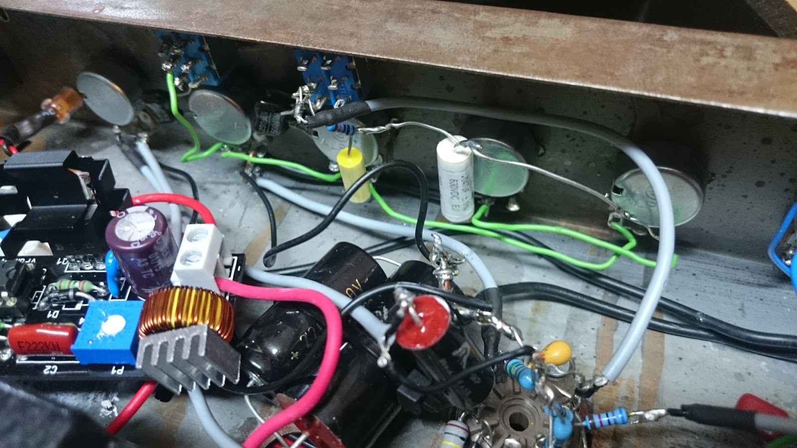
- PSU: IEC mains input with the fuse >> power switch >> PT 12VAC 50VA >> "micrelator" - a LDO linear regulated PSU board (with ST schottky diodes (I needed low dropout for normal function) and 10mF reservoir cap), set at 12,6V >> a) goes to LED, heaters, power amp module and banana plate b) TT Vpump - which provides plate voltage for the alembic
- banana booster with kick option, bypassable with a switch - first pot from the input jack - replaced Elkos with tantals >> https://www.tube-town.net/cms/?DIY/LoV-Projekte/Banana_Booster_%28engl%29
- Alembic tube bass preamp - schematic from the web with sweep and bright switches. In the schematic there is a 22uF cap drawn very close to the tube (looks like it is there more for "eating" the noise form the circuit than stopping the ripple), so I used it, paralled with another 2,2uF poly cap. Cap overkill again!
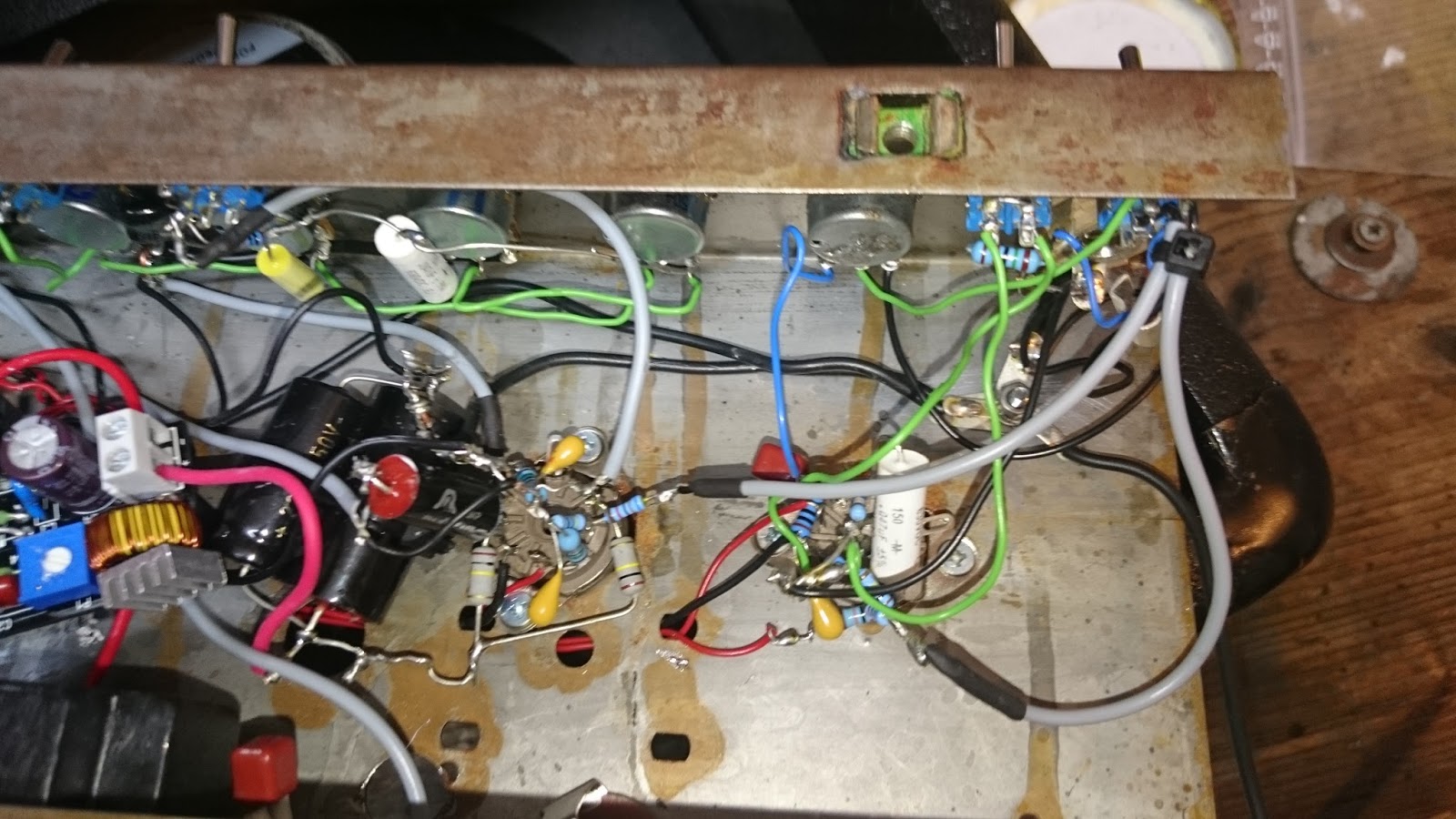
Both made in "point to point" manner, in a messy way - it is probably better to change the socket with all the attached components than to desolder them.
>> http://moosapotamus.net/ideas/alembic-f-2b-preamp/
- as the Endstufe Kemo 40W amp module (used previously) > speaker exit on the bottom of the chassis - to use also another speaker easily
>> http://www.kemo-electronic.de/en/Light-Sound/Amplifier-Splitter/M034N-Power-Amplifier-40-W.php
- grounding with solid wire (an also all non screened signal wire) - the resistance value is not so different, but I like that the wire stays in place even without regular attachment (stranded wires tend to wobble around in chassis and cause random parasitics in the process.)
Problems (and what I learned):
- PTP in this way is impossible to troubleshoot. At least I should have made the leads to the ground perpedicular to the socket (not to make a sort of a tent)
- shielded cables are a nice trap for shorting screen to the signal line - better a little longer unshielded end than dead silence due to short circuit
- with a choke used in TT vpump and my multimeter I cannot determine if it is shorted, because the multimeter leads have higher resistance than the coil
- Don't stuff too much in a chassis - don't be greedy - I thought I learned that previously, but again the same problem ... If I used factory made PCB it would have beeen different, but for the home production it is impossible
- things attached to the side of a chassis are hard to troubleshoot
- rust, if conditioned, can be a protective film for iron
Unsolved misteries:
- It was all working great, then I put the cable in Line out jack, and when I plugged it out, all died on me ->> could be a short between spk output and this jack
- I repaired the Vpump and it all worked, then I attached it (with protective washer, silicon shield and everything), and micrelator switched off due to schort circuit - where was it? Now I put a heatsink on a IRF741 and attached it trough the hole - and it all works great)
- how did the 68 resistor lead come in touch with DC lead a cm away
All in all, nice one.
It is really great to play it.
Maybe in some time I will get to make some more order in that chassis (and maybe reduce some noise) ...
With the experience in troubleshooting this project I also could have got enough knowledge to repair the "original" yamaha circuit. Besides from passives just two ICs basically - probably POweramp is fried.
But there is probably no chance I would put it back in. I wil find a box for it. And a speaker.
//
from TT forum
//
EDIT: Volume control started to "behave" and all became quite normal, when I replaced the (original) AX tube with the AU. Just the right amount of gain, and a fantastic growl with full ...


Ni komentarjev:
Objavite komentar